Rigging Pocket Guide (English)
Table of Contents
- RISK MANAGEMENT
- SLING INSPECTION REQS
- WARNING/MFG REQUIREMENTS
- SLING REMOVAL CRITERIA
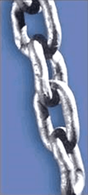
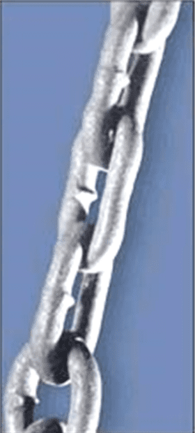
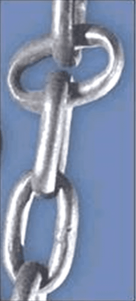
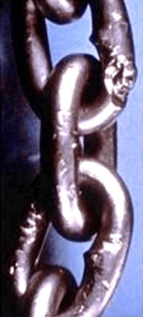
- CHAIN LINK DAMAGE SAMPLES
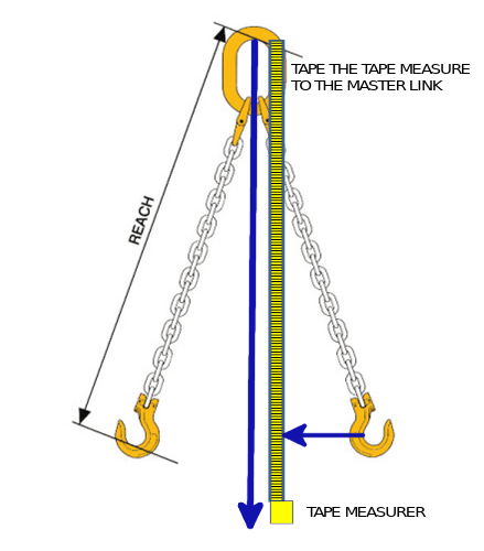
- CHAIN REACH DIMENSION
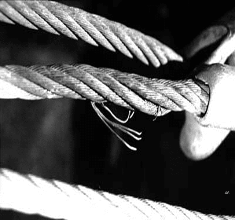
- VALLEY BREAK & LAY OF A WIRE ROPE
- HARDWARE REMOVAL CRITERIA
- TURNBUCKLE CAPACITY
- EYE BOLT USE AND CAPACITY
- SWIVEL HOIST RINGS AND CAPACITY
- WIRE ROPE CLIPS
- PLATE CLAMPS AND BEAM CLAMPS
- MAGNET LIFTERS
- SLING HITCHES
- D/d WIRE ROPE SLINGS
- D/d CHAIN SLINGS
- CALCULATING TENSIONS
- MAXIMUM INCLUDED ANGLES
- HOOKS
- SHACKLE USE AND CAPACITY CHART
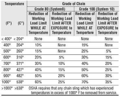
- SLING MAXIMUM TEMPERATURE
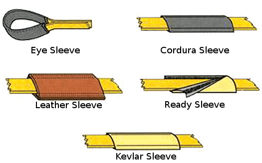
- SLING PROTECTION
- CAPACITIES WIRE ROPE CHAIN AND WEB SLINGS
- CAPACITIES ROUND SLINGS
- RIGHT TRIANGLE
- WEDGE SOCKET
- RIGGERS RESPONSIBILITIES
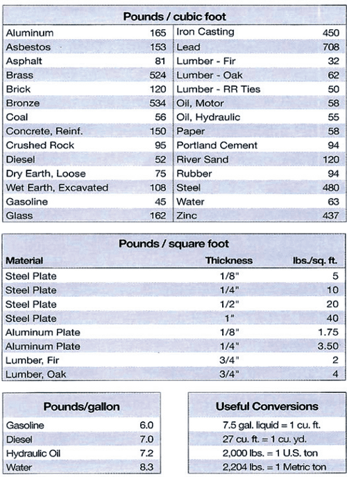
- ESTIMATING LOAD WEIGHTS
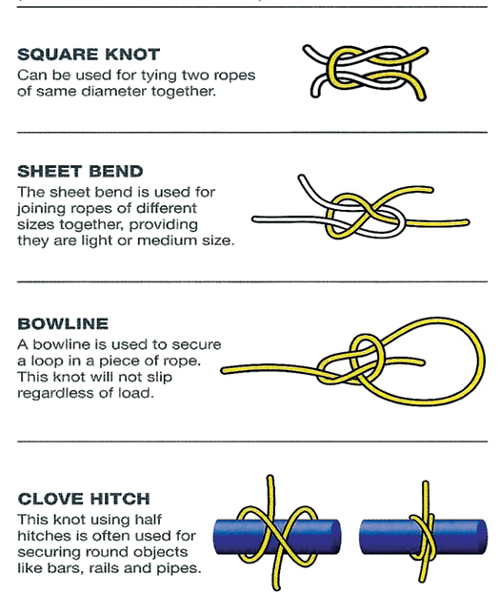
- KNOTS
- POWER LINE AWARENESS
- LOAD STABILITY AND CENTER OF GRAVITY
- SHOCK LOADING AND MANUAL HOIST
- DRIFTING LOADS
- CO-EFFICIENCY OF FRICTION
- RIGGING PLANS
Safety Information That You Need
At the heart of any effective safety program is a constant effort to ensure that employees have the proper knowledge and skill for all aspects of their job. Rigging and lifting clearly is an operation that has been shown to require knowledge and skills. Accidents also can harm your companies’ brand and reputation. Having a well-trained lift team can help mitigate, and possibly eliminate some of the hazards associated with using cranes. A safe lift depends on a number of people filling roles including operators, riggers, journeyman riggers, signal persons, crane owners, crane users, lift directors, supervisors, and the communication between those people.
B30.9-1.9.1-3 Slings shall be inspected by:
A qualified person as to whether it constitutes a hazard. And if so, what additional steps need to be taken to address the hazard and how it can be eliminated. And, shall have a thorough education, training, experience, skill and physical ability, as necessary, be competent and capable to perform the functions as determined by the employer or employer’s representative. Sling working load limits (WLL) are based on items being in acceptable condition before being used per ASME B30.9, OSHA 1910.184 and the manufacturer’s recommendations and limitations for use.
Working Load Limit (W.L.L)
The MAXIMUM load that shall be applied in direct tension to undamaged straight length of a sling or hoisting equipment.

WLLS are based on the following factors:
- Type of hitch being used
- Material strength
- Design factor
- Angle of loading
- Diameter of the object (D/d)
- Manufacturer’s limitations

Safety Warnings:
Are of the utmost importance and anyone purchasing and using items must understand all warnings and other information on the product being used. Products are sold with express understanding that the purchaser is thoroughly familiar with the correct application and safe use for which they were intended.
Remember:
Any product will break if abused, misused or overused. Any well-designed and well-built product can become a hazard in the hands of careless users. It is impossible to list all of the possible dangers and misapplications associated with the use of products.
Minimum sling inspection intervals:
- Prior to each use
- Beginning of each shift
- Monthly to quarterly depending on severity of use by a designated competent person
- Annually by a dedicated, competent person
ASME B30.9-1.7.1 2018 sling identification requirements that shall be permanently affixed to the sling:
- Manufacturer’s name
- Sling size
- Sling grade (chain and wire rope) materials used (web and round slings)
- Sling reach (chain)
- Working load limit and the angle upon which its based
- Number of branches if more than one
- Missing, or illegible identification or tag
- Evidence of heat damage, or caustic, or acid burn
- Melting, or charring (synthetic)
- Holes, tears, cuts, or snags (synthetic)
- Visible red threads (web slings)
- Weld spatter
- Broken or worn stitching (synthetic)
- Excessive abrasive wear
- Knots
- Discoloration and brittle or stiff areas (synthetic)
- Fittings that are pitted, corroded, cracked, bent twisted, deformed, gouged, broken, or wear of more than 10%
- Increase in the reach dimension or stretched (chain)
- Lack of ability of the fittings to hinge freely
- Broken wires for strand-laid single-part wire rope slings, 10 randomly distributed broken wires, or 5 broken wires in one strand in one rope lay, or 1 core or (valley break), or 1 broken wire at a fitting
- Kinking, crushing, birdcaging, or other damage resulting in damage to the rope structure (wire rope slings)
- Hooks for wear ASME B30.10
- Rigging hardware removal ASME B30.26
- Other conditions including visible damage, that may cause doubt as to the continued use of the sling
NOTE: A MISSING TAG IS CONSIDERED A REPAIR B30.9 SLING REPAIR SHALL ONLY BE DONE BY THE SLING MANUFACTURER OR QUALIFIED PERSON AND SHALL COMPLY WITH PROOF LOAD REQUIREMENTS.
With the following information on the tag
- Identify Manufacturer
- Size of the chain
- Grade of the chain
- Reach dimension
- Serial number
- Number of legs
- Working load limit
This happens when wire fractures between the strands coming from the core it is usually caused by a shock load
Just 1 broken wire requires the sling to be removed from service!

Identification Requirements
- Trademark or name of manufacturer
- Size or rated load
- Grade for alloy eyebolts
Rejection Criteria:
- Illegible or missing identification
- Any distortion, bends, twists, stretching, elongation, cracking
- Nicks & gouges
- Heat damage
- Thread damage
- Wear 10% of original diameter
- Corrosion or pitting
- Modifications


| WORKING LOAD LIMIT (lbs.) | ||
| End Fitting Types | ||
| Size (Inches) |
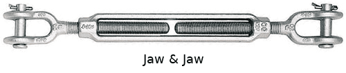
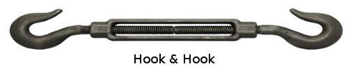
Hook & Eye Hook & Hook |
Eye & Eye Eye & Jaw Jaw & Jaw |
| 1/4 | 400 | 500 |
| 5/16 | 700 | 800 |
| 3/8 | 1,000 | 1,200 |
| 1/2 | 1,500 | 2,200 |
| 5/8 | 2,250 | 3,500 |
| 3/4 | 3,000 | 5,200 |
| 7/8 | 4,000 | 7,200 |
| 1 | 5,000 | 10,000 |
| 1-1/4 | 6,500 | 15,200 |
| 1-1/2 | 7,500 | 21,400 |
WARNING
TURNBUCKLES TO BE USED FOR
IN-LINE LOADING ONLY
EYEBOLTS AND SWIVEL HOIST RINGS


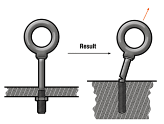
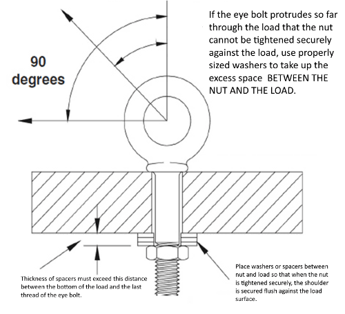
EYEBOLTS MAXIMUM TEMPERATURE 275°
THIS IS A SHOULDERED EYEBOLT IT CAN BE PULLED IN THE PLANE OF THE EYE AT NO GREATER THAN 45° AND HAS ONLY 25% OF ITS CAPACITY

| Size (in.) |
WORKING LOAD LIMIT (lbs.) | |||
| 0° True Vertical | 75° 55% of FULL WLL | 65° 35% of FULL WLL | 45° 25% of FULL WLL | |
| 1/4×20 | 500 | 275 | 175 | 125 |
| 5/16×18 | 900 | 495 | 315 | 225 |
| 3/8×16 | 1,300 | 715 | 455 | 325 |
| 7/16×14 | 1,800 | 990 | 630 | 450 |
| 1/2×13 | 2,400 | 1,320 | 840 | 600 |
| 5/8×11 | 4,000 | 2,200 | 1,400 | 1,000 |
| 3/4×10 | 5,000 | 2,750 | 1,750 | 1,250 |
| 7/8×9 | 7,000 | 3,850 | 2,450 | 1,750 |
| 1×8 | 9,000 | 4,950 | 3,150 | 2,250 |
| 1-1/8×7 | 12,000 | 6,600 | 4,200 | 3,000 |
| 1-1/4×7 | 15,000 | 8,250 | 5,250 | 3,750 |
| 1-1/2×6 | 21,000 | 11,550 | 7,350 | 5,250 |
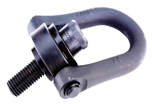
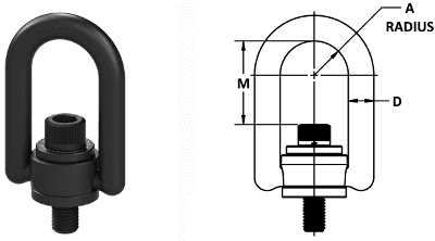
| Size (in.) |
Rated Load (lbs.) | Torque Load (lbs-ft) | Dimensions (in.) | ||
| A | D | M | |||
| 1/4-20 | 500 | 5 | 0.65 | 0.44 | 1.57 |
| 5/16-18 | 800 | 7 | 0.65 | 0.44 | 1.51 |
| 3/8-16 | 1,000 | 12 | 0.65 | 0.44 | 1.45 |
| 1/2-13 | 2,500 | 28 | 1.00 | 0.75 | 2.56 |
| 5/8-11 | 4,000 | 60 | 1.00 | 0.75 | 2.44 |
| 3/4-10 | 5,000 | 100 | 1.00 | 0.75 | 2.31 |
| 3/4-10 | 7,000 | 100 | 1.00 | 1.00 | 2.31 |
| 7/8-9 | 8,000 | 160 | 1.40 | 1.00 | 3.07 |
| 1-8 | 10,000 | 230 | 1.40 | 1.00 | 2.95 |
| 1-1/4-7 | 15,000 | 470 | 1.40 | 1.00 | 3.74 |
| 1-3/8-6 | 20,000 | 670 | 2.00 | 1.25 | 3.62 |
| 1-1/2-6 | 24,000 | 800 | 2.00 | 1.25 | 3.49 |
| 2-4-1/2 | 30,000 | 800 | 2.00 | 1.25 | 3.49 |
| 2-8 | 30,000 | 800 | 2.00 | 1.25 | 3.49 |
| Rope Diameter (in.) | No. of Clips | Turnback (in.) | Torque (ft-lbs)(unlubed bolts) |
| 1/8 | 2 | 3-1/4 | 4-1/2 |
| 3/16 | 2 | 3-3/4 | 7-1/2 |
| 1/4 | 2 | 4-3/4 | 15 |
| 5/16 | 2 | 5-1/4 | 30 |
| 3/8 | 2 | 6-1/2 | 45 |
| 7/16 | 2 | 7 | 65 |
| 1/2 | 3 | 11-1/2 | 65 |
| 9/16 | 3 | 12 | 95 |
| 5/8 | 3 | 12 | 95 |
| 3/4 | 4 | 618 | 130 |
| 7/8 | 4 | 20 | 225 |
| 1 | 5 | 26 | 225 |

WARNING
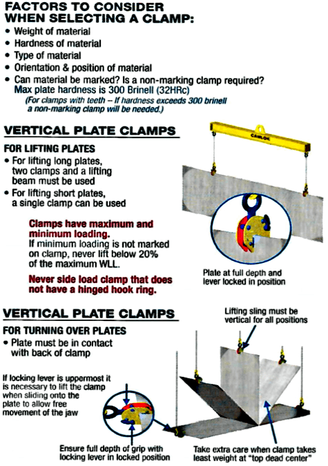

Vertical Plate Lifting Clamps
- Lift and turn over flat plate 180º or transport in the vertical position.
- For short plates one clamp can be used to lift.
- For long plates use a beam with vertical slings on each end connected to each clamp.
- Avoid lifting load 20% below the rated capacity of the side of the clamp.
- Select a clamp as close to the max loading as possible, this will insure full penetration of teeth into plate.
- Max surface 300 Brinell/32 RC. Do not lift plates harder than the teeth of clamp.

BOLTS: All bolts should have sufficient plain length to pass through half the component. Check integrity & tightness.
NUTS: All nuts when tightened should have 2 threads protruding. All nits should be locked with Loctite grade 270, nylon insert, or self-cleaving. Check for integrity & tightness.
CHAIN: All chain should be tested in accordance with ASME B30.9 recommendations.


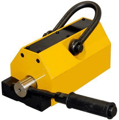
There have been recent changes to magnet inspections and testing that everyone needs to be aware of. The ASME 820.20-2018 standard states Lifting Magnets should have an annual Breakaway Test to verify the magnet meets its design factor.
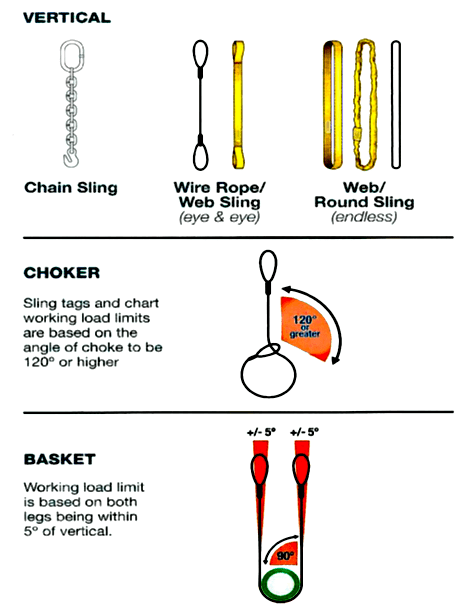
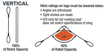

| Angle of Choke | Rated Capacity |
| Over 120° | 100% |
| 90° – 120° | 87% |
| 60° – 89° | 74% |
| 39° – 59° | 62% |
| 0 – 29° | 49% |

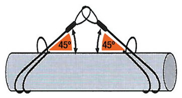

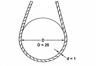
| D/d Ratio | Capacity |
| 25/1 | 100% |
| 20/1 | 92% |
| 10/1 | 86% |
| 4/1 | 75% |
| 2/1 | 65% |
| 1/1 | 50% |


| D/d Ratio | Capacity |
| 6/1 | 100% |
| 5/1 | 90% |
| 4/1 | 80% |
| 3/1 | 70% |
| 2/1 | 60% |
| 1/1 | Not Recommended |
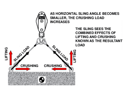

This tension is also referred to as the
LOAD ANGLE FACTOR (L.A.F.)
IT IS CALCULATED BY DIVIDING THE S OR SLING LENGTH BY THE H OR HEIGHT TO THE SAME POINT ON THE SLING
WARNING
ALWAYS MAKE SURE TO VERIFY THE CAPACITY ON THE SLING YOU ARE USING, IT MAY VARY FROM THE SLING CAPACITY IN THIS BOOKLET
| Horizontal Angle | Load Angle Factor |
| 30° | 2 |
| 35° | 1.742 |
| 40° | 1.555 |
| 45° | 1.414 |
| 50° | 1.305 |
| 55° | 1.221 |
| 60° | 1.155 |
| 65° | 1.104 |
| 70° | 1.064 |
| 75° | 1.035 |
| 80° | 1.015 |
| 85° | 1.004 |
| 90° | 1 |
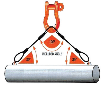
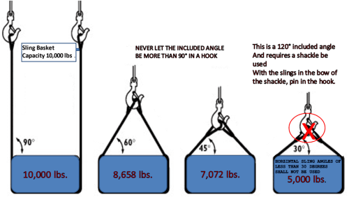
The maximum included angle with two or more slings is listed below for hooks, master links and shackles.


- Deformation – any visibly apparent bend or twist from the plane of the unbent hook
- Throat Opening – Any distortion causing an increase in throat opening of 5%, not to exceed ¼” or as recommended by the manufacturer
- Wear – Any wear exceeding 10% (or as recommended by the manufacturer) of the original section dimension of the hook or its load pin
| Angles in Degrees | Working Load Limit Reduction |
| 0° to 10° | 0% |
| 11° to 20° | 15% |
| 21° to 30° | 25% |
| 31° to 45° | 30% |
| 46° to 55° | 40% |
| 56° to 70° | 45% |
| 71° to 90° | 50% |

WARNING

Shackles can be connected together, or point loaded

Always attach the slings to the bow of the shackle, pin in the hook

The bow of the shackle should always be in the running part of the sling pin in the eye of the sling

When using a single sling, load should stay centered or capacity reductions are necessary

When using in a wire rope sling always use the next size larger
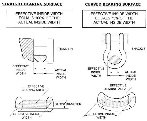
The shackle must be the next size larger than the wire rope sling diameter to achieve full capacity of the sling
ASME B30.26 has the following statement regarding screw pin shackles:
The screw pin threads shall be fully engaged and tight and the shoulder should be in contact with the shackle body.
Thus, contrary to popular belief, you should never back off the screw pin before use. The shackle pin should be a minimum of hand tight before the lift begins.
SHACKLE INSPECTION


Shackles are designed and rated for in-line applied tension. You can attach multiple slings in the body of the shackle without reducing the capacity, provided that the shackle is symmetrically loaded and the included angle does not exceed 120°.
SHACKLE INSPECTION

| Size (in.) | WLL (tons) | WLL (lbs.) | Pin Diameter (in.) | W dim. (in.) |
| 3/16 | 1/3 | 667 | 0.25 | 0.38 |
| 1/4 | 1/2 | 1,000 | 0.31 | 0.47 |
| 5/16 | 3/4 | 1,500 | 0.38 | 0.53 |
| 3/8 | 1 | 2,000 | 0.44 | 0.66 |
| 7/16 | 1-1/2 | 3,000 | 0.50 | 0.72 |
| 1/2 | 2 | 4,000 | 0.63 | 0.84 |
| 5/8 | 3-1/4 | 6,500 | 0.75 | 1.06 |
| 3/4 | 4-3/4 | 9,500 | 0.88 | 1.28 |
| 7/8 | 6-1/2 | 13,000 | 1.00 | 1.44 |
| 1 | 8-1/2 | 17,000 | 1.13 | 1.72 |
| 1-1/8 | 9-1/2 | 19,000 | 1.25 | 1.84 |
| 1-1/4 | 12 | 24,000 | 1.38 | 2.03 |
| 1-3/8 | 13-1/2 | 27,000 | 1.50 | 2.25 |
| 1-1/2 | 17 | 34,000 | 1.63 | 2.41 |
| 1-5/8 | 20 | 40,000 | 1.75 | 2.66 |
| 1-3/4 | 25 | 50,000 | 2.00 | 2.94 |
| 2 | 35 | 70,000 | 2.25 | 3.28 |
| 2-1/2 | 55 | 110,000 | 2.75 | 4.13 |
| 3 | 85 | 170,000 | 3.25 | 5.00 |
| 3-1/2 | 120 | 240,000 | 3.75 | 5.50 |
Shackles can be used to connect slings

WARNING
NEVER TIE SLINGS TOGETHER
OR DIRECTLY TO LIFTING BOLTS/LUGS

Shackles can be used to connect slings
WARNING
NEVER TIE SLINGS TOGETHER
OR DIRECTLY TO LIFTING BOLTS/LUGS
ASME B-30.9 Standard for slings states that “…Sling users SHALL be trained in the selection, inspection, cautions to personnel, effects of environment, and rigging practices…”

SHACKLE SIZE IS IMPORTANT
AND
NEVER EVER
STACK THE SLINGS ON TOP OF ONE ANOTHER


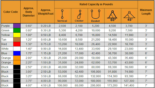
| Vertical Rated Capacity | Vertical | Basket |
| Minimum Shackle Size Required | ||
| 2,600 | 1/2″ | 3/4″ |
| 5,300 | 3/4″ | 1″ |
| 8,400 | 7/8″ | 1-3/8″ |
| 10,600 | 1″ | 1-1/2″ |
| 13,200 | 1-1/4″ | 1-5/8″ |
| 16,800 | 1-3/8″ | 1-3/4″ |
| 21,200 | 1-1/2″ | 2″ |
| 25,000 | 1-5/8″ | 2-1/2″ |
| 31,000 | 1-3/4″ | 2-1/2″ |
| 40,000 | 2″ | 2-3/4″ |
| 53,000 | 2-1/2″ | 3″ |
| 66,000 | 2-1/2″ | 3-1/2″ |
| 90,000 | 3″ | 4″ |
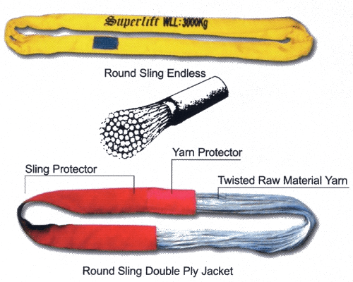
NOTE: Round sling strength is affected by the size of the connection hardware. For special applications wherein a Retained design factor of 5 is required to be maintained, contact the sling manufacturer, as a capacity reduction of 20% may be appropriate in order to satisfy this criteria.

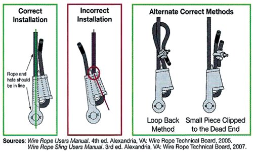
Proper Use of Wedge Sockets
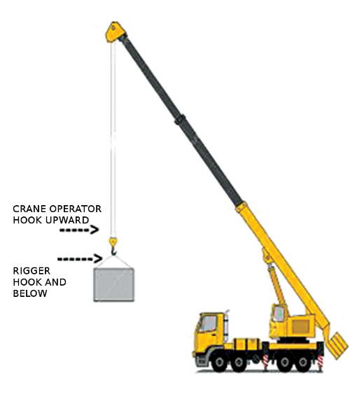
OUTRIGGER SUPPORT IS A DUAL RESPONSIBILITY OF THE LIFT DIRECTOR AND THE CRANE OPERATOR
- a site assessment for hazards in the surroundings such as but not limited to electrical, steam, vehicles, personnel, roads, ground conditions, pedestrian traffic, narrow aisles, drop-offs, debris, floor obstructions, overhead obstructions and environmental conditions.
- ensuring the weight of the load and its approximate center of gravity have been obtained, provided, or calculated.
- selection of the proper rigging equipment, inspecting it and complying with the applicable operating practices according to OSHA, ASME and the manufacturer of the equipment.
- ensure the rated load if the rigging equipment is sufficient for the load being lifted, based on the number of legs, hitch configuration, angles, manufacturers limitations and environment.
- ensure all rigging is properly attached to hooks, shackles, slings or other load handling devices.
- ensure all rigging equipment is adequately protected from abrasion, cutting, or other damage during load handling activity.
- the load is rigged in a manner to ensure balance and stability during the lift activity.
- knowing and understanding the applicable signals for the equipment in use.
- installing and using a tag line or taglines when load control is required.
If the equipment and or attachments are within 20’ of the 360 degree reach of the crane, a dedicated spotter must be used and:
- Positioned to effectively gauge the clearance (distance) from the line.
- Give timely information to the operator to avoid the crane breaching the safe distance from the line.
- He/She must be a trained spotter that has been evaluated. Their sole job is to watch the crane and the power line.
| Voltage (nominal, kV, alternating current) | Minimum clearance distance (feet) |
| up to 50 | 10 |
| over 50 to 200 | 15 |
| over 200 to 350 | 20 |
| over 350 to 500 | 25 |
| over 500 to 750 | 35 |
| over 750 to 1,000 | 45 |
| over 1,000 | (as established by the utility owner/operator or registered professional engineer who is a qualified person with respect to electrical power transmission and distribution) |
Note: The value that follows “to” is up to and includes that value. For example, over 50 to 200 means up to and including 200kV.
Section 1926.1409
Power line safety (over 350kV)
The requirements of S 1926.1407 and 1926.1408 apply to power lines over 350 kV except:
a) For power lines at or below 1000kV, wherever the distance “20 feet” is specified, the distance “50 feet” must be substituted; [S 1926.1409(a)]
b) For power lines over 100kV, the minimum clearance distance must be established by the utility owner/operator or registered professional engineer who is a qualified person with respect to electrical power transmission and distribution. [S 1926.1409(b)
OSHA SAY’S IT’S USERS RESPONSIBILITY TO STAY OUT OF THE WAY OF THE LOAD
THE CLOSEST YOU SHOULD GET IS ARMS REACH

Have you performed a TEST LIFT to verify stability?
Properly Rigging to the Center of Gravity
It is important that the CG is directly under the crane hook.
STABLE
The hook lift point is directly above the CG.
Lift points are ABOVE the CG.

Safe Hoist and Crane Operations
Smooth, steady application of lifting force
- Allows hoist and rigging to adjust to change
- Minimizes spin
- Reduces wear on wire and synthetic rope
NO Shock loading – A 4″ DROP TRIPLES THE LOAD
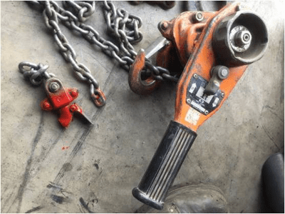
MANUAL HOIST
NEVER WRAP THE CHAIN AROUND THE LOAD
THIS IS WHAT CAN HAPPEN IF YOU WRAP THE CHAIN AROUND THE LOAD
THESE HOISTS ARE ONLY MADE FOR A STRAIGHT PULL
USE SLINGS AROUND THE OBJECT BEING LIFTED
Hooks on Hoists
Required ASME B30.16/B30.21
Hooks shall be equipped with latches unless use of the latch creates a hazardous condition
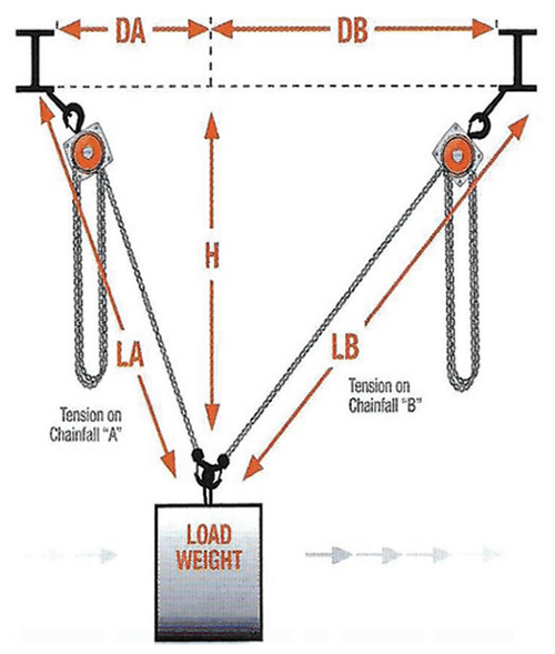
THE LB ÷ H GIVES YOU THE LOAD ANGLE FACTOR FOR THE RIGHT SIDE.
THE LA ÷ H GIVES YOU THE LOAD ANGLE FACTOR FOR THE LEFT SIDE.
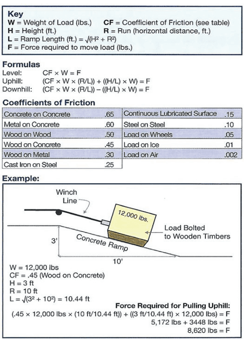
Level & Incline Planes
- The head director must communicate to all personnel involved in the lift the lift sequence and complete process.
- Verify or determine center of gravity of load.
- Verify or determine weight of load.
- Choose slings and rigging hardware that will provide sufficient capacity and load control. Use a tag line when necessary.
- Ensure slings and rigging hardware are properly aligned or used correctly.
- All rigging gear must be inspected prior to making the lift.
- Determine exactly how the load will be lifted, moved and set down.
- Consider any special environmental conditions, *wind, *heat/cold/ice (what effect do they have), *corrosive atmosphere.
- Determine manpower requirements for the rigging crew.
- Identify obstructions and hazards, *Power Lines, *Live chemical, Steam lines, *Traffic control, *Tight fits, *Pinch points.
- Everyone involved with lift must: *Review plan, *Understand their role and *Sign off before lift begins.
29 CFR 1926, SUBPART N ANSI/
ASME B-30.7 SERIES
RESPONSIBILITIES
Management Responsibilities
- Make determinations of critical lifts
- Provide supervisor & employee training
- Provide safe and proper equipment for critical lifts
- Provide inspection procedures
Supervisors Responsibilities
- Follow guidelines and inspection procedures
- Supervise all critical lifts
- Ensure employees have adequate operational knowledge & experience
- Immediately remove from service any equipment that fails inspection
Employees Responsibilities
- Follow lifting & rigging procedures
- Immediately report any problems with equipment of procedures
- Not attempt any critical lifts unless authorized & approved assigned the PIC or (person in charge) need not be in the manager’s organization.